Formatting the Radar in a Radar Chart
This topic introduces how to format a Radar chart.
- Right-click any line which connects two value nodes in the radar chart and select Format Radar on the shortcut menu, or double-click any line connecting two value nodes in the radar. The Format Radar dialog appears.
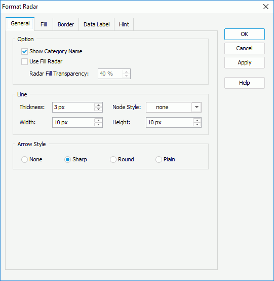
- In the General tab, specify the general settings of the radar.
In the Option box, set whether or not to show the category name in the radar, check Use Fill Radar to fill the areas formed by value nodes of a same data series in the radar and set the transparency of the fill accordingly.
In the Line box, set the thickness, node style and node width and height for the lines connecting the value nodes in the radar.
In Arrow Style box, specify the style for arrows of the numeric axes in the radar.
- In the Fill tab, set the color pattern to fill the radar areas, which will also be applied to the corresponding value nodes.
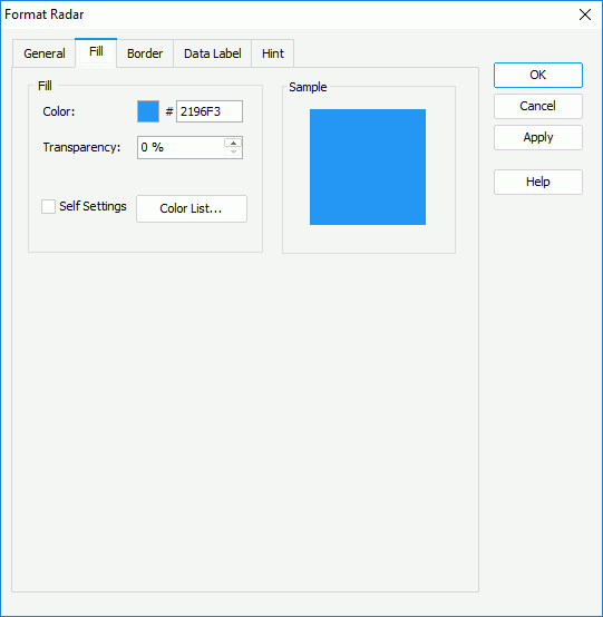
To specify the color pattern, first make a choice for the Self Settings checkbox: when Self Settings is unchecked, the color pattern specified here will be synchronized to the Pattern List property on the chart object in the Report Inspector, which can also be applied by data markers of other subtypes if the chart is a combo chart; when Self Settings is checked, it indicates the color pattern is private to the current data markers themselves (the radar areas in this case), which can be remembered and applied to the data markers of a new type automatically if later you change the type of the chart. Then specify the color and the transparency of the color schema to fill the selected radar areas in the same data series (to change the color, select the color indicator and select a color from the color palette or input the hexadecimal value of a color directly in the text box). You can also select the Color List button to specify the color pattern for radar areas in the same data series respectively in the Color List dialog.
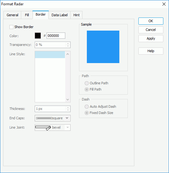
- In the Border tab, check Show Border if you want to show the border of the radar, then set properties of the border including the border color, transparency, line style, thickness, end caps style, and line joint mode. You can also specify whether the border is to be outlined, and whether or not to automatically resize the border dashes if the border is drawn with dashes.
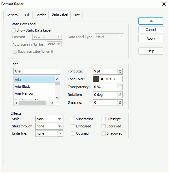
- In the Data Label tab, check Show Static Data Label if you want to show static data labels for every value node on the radar, then decide the position of the label related to the node, the display type for data values in the labels, whether to scale big and small numbers, and whether to hide the label whose value is 0. In the Font and Effects boxes, set the font formats and effects of the data labels.
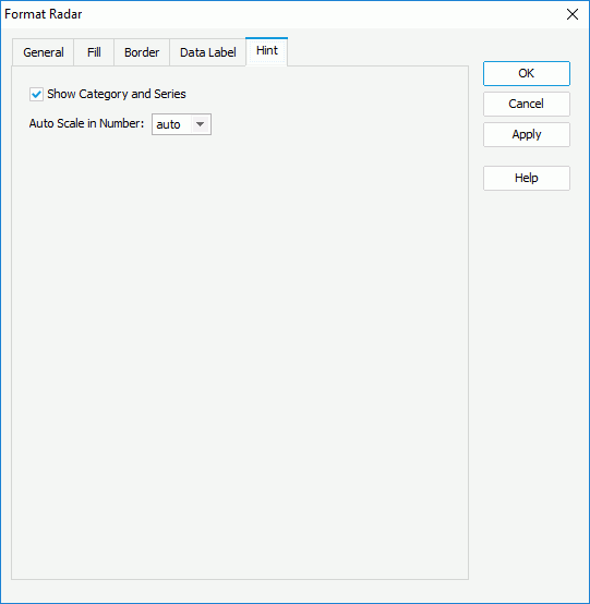
- In the Hint tab, specify whether to
include the category and series values and whether to scale big and small numbers in the radar hint. A hint displays the value a node in the radar chart represents when the mouse pointer points at the node in Logi JReport Designer view mode, in HTML result, or at server runtime. To make the hint shown, you need to make sure the Show Tips property in the Report Inspector is set to true.
- Select OK to accept the changes and close the dialog.
 Previous Topic